
Bi-directional load-test plates: drawing and interface requirements
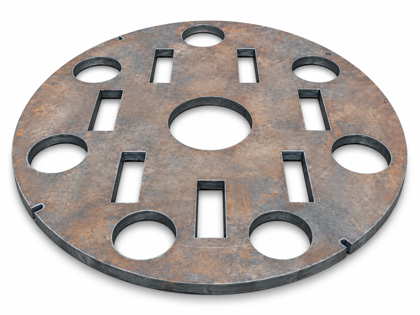
A bi-directional static axial load plate is a fabricated component within a project-specific testing assembly. The plate should be coordinated with the test-system designer. It is not, by itself, a complete hydraulic load cell, instrumentation package or certified testing system.
Bi-Directional Static Axial Load Plate
How to specify the right configuration
Provide the engineered plate geometry, thickness, openings, interface dimensions and material requirements. Identify contact and attachment details with the surrounding assembly. Custom size means the drawing must be defined; it does not imply a published load capacity.
Catalog specifications and listed options
Custom-made load plate for bi-directional static axial load testing. Plate diameter, thickness, openings and layout are manufactured to confirmed project drawings. Include the required dimensions, testing arrangement and design requirements with your quotation request.
- Custom sizes
Assembly review and inspection
Ask the responsible engineer to confirm the load path, plate design and inspection requirements. Include tolerances and documentation in the fabrication scope. Keep the plate, hydraulic components and instrumentation separately identified so a quotation does not imply equipment that was never specified.
What drawing is needed for a bi-directional load plate?
Provide the confirmed testing layout, plate diameter, thickness, openings and connection details. Dimensions and design requirements must come from the engineered test arrangement.
Preparing a quotation request in Saudi Arabia
- Identify the rig model, product, quantity and application; include the ground profile when specifying a cutting tool.
- Send a dimensioned drawing or clearly scaled photos. Identify mating components and distinguish measured dimensions from estimates.
- State the delivery city, required date and project documentation requirements. Confirm the included components before ordering.